Volksduino Build Instructions
This guide will walk you through the order of installing components, with pictures of every step. The board is well-labelled, too, if you're an experienced kitbuilder. Just remember: C1, C2, and the 3.3V regulator remain unpopulated.
These instructions work their way from the top-right corner of the board, and proceed to work counter-clockwise from there. If you get lost, compare the image of the last step to this one; hopefully it's easy to find the next component in the counter-clockwise pattern. Every step does one thing, and almost all of them involve only one component.
Go ahead and plug in your iron, and do a quick check over the parts list to make sure you've got everything in front of you. If not, email us, and we'll mail whatever you're missing.
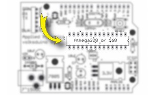
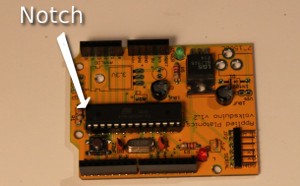
Install the socket (mind the notch)
First, solder down the socket. Note that it has a little notch on one end; this end should face to the right of the board. There's a little notch in the outline on the PCB to help identify this.
It's usually best to hold the socket in with a finger, put a length of solder in your third hand, and solder down the corners this way. After that, it's pretty easy to go around and finish the other pads.
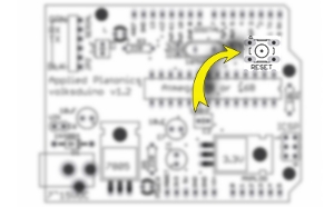
Install the reset switch
The reset switch goes in next, in the upper right corner. It just pops in and is soldered down.
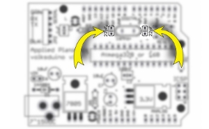
Install the crystal's caps
Next, put in the 22pF capacitors. These are the little orange-red circle caps, and they belong right above the socket.
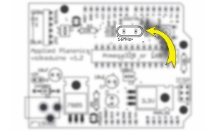
Install the crystal
After the two crystal caps are in, insert and solder down the crystal.
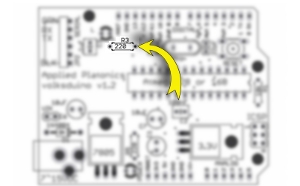
Put in R3
Continue to the left, putting in R3. This is a 220Ω resistor; the color code for that is Red-Red-Brown. (Sorry if I just ruined a chance for you to practice the code!)
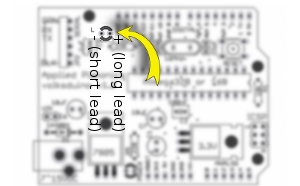
Add the red LED (careful of polarity)
Put in the red LED next. Be careful here! LEDs are
polarized, which means that you need to put it in the right way.
There's a little plus on the board to the socket side of the
LED. This means that the longer lead should go in the hole
nearest the socket.
(The picture here is from a
different angle than all the others. It's from the top of the
board, showing that the long lead goes into the one by the
socket. )
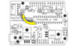
Install C3
C3 is a little hard to see in the picture, so I hung a black arrow over it. This is the .1μF capacitor, which is the small yellow cap.
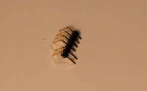
Tweak the serial header slightly
These 6 pin right-angle headers come from the factory with the plastic hiked up like an old man's trousers. Why? Who knows. But it looks goofy in the board if left like this, and serial connections aren't physically sound. So, very carefully use a pair of pliers to push each pin through the header like the two at the bottom here.
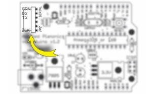
Install the serial header
Install the serial in the upper-left corner, as shown. This is another opportunity to use the "solder in the third hand" technique, but be careful! Whichever pin is soldered down will get really hot. The others will stay cool, so carefully hold the pins in with one finger and tack down one end. After that, solder the rest as normal.
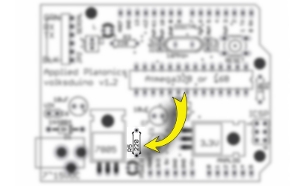
Place C6 (careful of polarity)
Next, install C6. This is a polarized component, so it must be put in facing the right direction. C6 is one of the 10μF capacitors, which come in little dark blue cans. One side has a sporty white stripe: this is the negative side. Of course, the circuit board has the positive side labelled (there's a little plus inside the circle, on the side closest to the socket). So, put it in with the white stripe away from the socket.
Also, be careful not to cook this component. If the soldering iron is on it for more than 15 seconds, give it a minute or so to cool down.
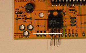
Bend the leads on the 7805
As shown in the image, the 7805 needs to have its legs bent. The best way to do this is to hold the legs with a pair of needlenose pliers, and use fingers to bend them down individually. That is, the pliers should be touching the black plastic, and each leg gets bent individually.
Be careful with this step: if the legs are bent more than 3 or 4 times, they have a habit of breaking.
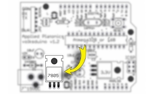
Solder in the 7805
Next, solder down the 7805. Note that the metal back is up against the circuit board. This connects to ground, so ensure it's not touching any of the shiny pads on the board.
(Also, these things conduct heat surprisingly well, so don't touch it immediately after soldering it down.)
Install R5, 220Ω
Next, install R5. This is another 220Ω resistor (Red-Red-Brown)
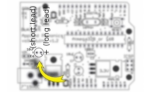
Install the green power LED (careful of polarity)
Put the green power LED, long lead to the right, in the spot labeled, unsurprisingly, "POWER." There's a little "+" muddled into the "POWER" label, showing where the longer lead should go.
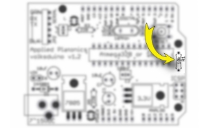
Place R1, 10kΩ
Next, install R1, the 10kΩ resistor. It is found right next to the socket, on the far right of the board.
Congratulations! That's the last component! Now it's down to headers and the Atmega328 itself!
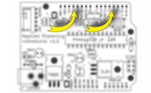
Install the top headers
Installing the headers along the top of the board provides another opportunity to work the one-finger-hold, solder-in-third-hand fu.
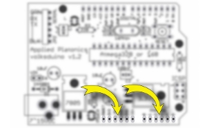
Install the bottom headers
Placing the bottom headers is the last chance to show off your third-hand-soldering technique. Once these are done, there's no more soldering to do!

Flatten the Atmega328 pins
The Atmega328 comes with its pins splayed out a bit. These need to be straightened up a bit to fit the chip into its socket.
Gently straighten the Atmega328's pins on the tabletop. Note that the pressure on the thumbs is on the body of the chip, not the pins: the goal is to gently rotate the whole chip, keeping all the pins nice and straight.
Go carefully and slowly, and check your work afterwards by eyeballing the rows of pins. Make sure they're straight.
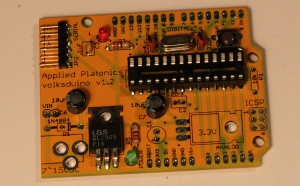
Socket the Atmega328 (mind the notch)
Look at the Atmega328; on one end, there will be a little notch. That notch should match the one on the board and the socket. If the socket and the board don't agree, listen to the board.
Once all the pins are lined up on the socket, gently push it down. There should be a small click as it gets into place. Give it a quick once-over to make sure nothing is obviously wrong with the chip, and you're done!
Things to check:
- Notches! Are the notches lined up? This is really important.
- LEDs Do you have both LEDs in the right way?
- Soldering Double-check that every pin has been soldered. It's very easy to miss one of the pins on the socket or the headers, since there are so many.
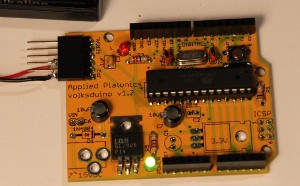
Power up!
If everything seems to be in order, power it up! Plug in a USB-TTL cable; the POWER LED (green) should go on, and the L LED (red) should blink.
(This photo is cheating a bit, by using a custom battery pack. This is used in Volksduino classes to test boards quickly, since not all students have laptops with them.)

Blink!
Once you see this blinking, you're done with the smallest step in your Volksduino journey. You now have a platform you can develop with, using off-the-shelf shields, custom circuit boards, and the Arduino IDE. Congratulations, and happy hacking!
